CIVIL WORKS GUIDELINES FOR MICRO-HYDROPOWER IN NEPAL
127
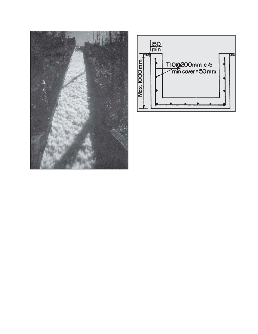
Figure 8.6 Reinforced concrete tailrace channel
Photo 8.6 Tailrace channel of the Jhankre mini-hydro scheme
allowed, within the limits given in Table 4.1. Note that at
higher velocities a stronger grade of mortar or concrete is
required to resist erosion. Reinforced concrete may be
economic for a steep channel, as shown in Figure 8.6.
Note that the downstream end of the tailrace must be arranged
so that there is no danger of erosion either by the river or by
the flow from the tailrace. Ideally the discharge point should
be onto rock or large boulders. In erodible material a stilling
basin may be required to dissipate the energy from a steep
tailrace channel.
8.5.3 DESIGN OF TAILRACE PIPE
If due to site conditions, a pipe is required for the tailrace, the
design procedure discussed in Section 4.5 (Headrace pipe,
Chapter 4) should be used to size the pipe. Similar to a tailrace
channel, a higher headloss can be allowed for the pipe.
If HDPE pipe is used, the velocity should be limited to 3m/s
and the pipe should be laid to a uniform gradient. Higher
velocities or non-uniform gradient can result in air
entertainment and surge problems.
If possible, the tailrace should empty onto large rocks at the
riverbank so that there is no erosion at the confluence.
8.6 Checklist for powerhouse and tailrace
Is the powerhouse located above the appropriate flood
level?(Refer to Section 8.2) Is the powerhouse area stable?
Refer to Chapter 9 for further details on stability.
Has adequate space been allowed inside the powerhouse such
that all equipment can fit in and permit access without
difficulty? Has the machine foundation been sized such that
it is safe against overturning, bearing and sliding? Also, be
sure to structurally isolate the machine foundation.
Is a channel or a pipe adequate for the tailrace?
Have the velocity limits been checked?
Is the tailwater likely to cause erosion at the riverbank?